73 Results
View results:
Sort by:

Reading out Nodal Deformation with Python
How can I read out the deformation at a certain node using the Python program?
.png?mw=640&hash=b185b93d198dbab2b9f9520baa36571a8c8ed367)
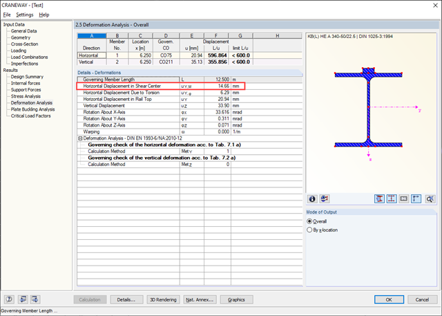
SLS Rotational Deformations of Crane Runway Girder
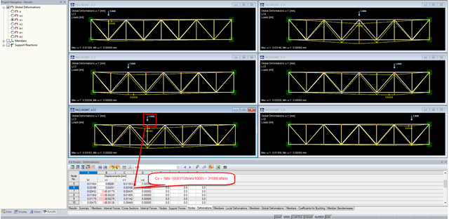
Is it possible in the CRANEWAY software to obtain the SLS rotational deformations of a continuous beam at the supports for an isostatic beam in the web plane?
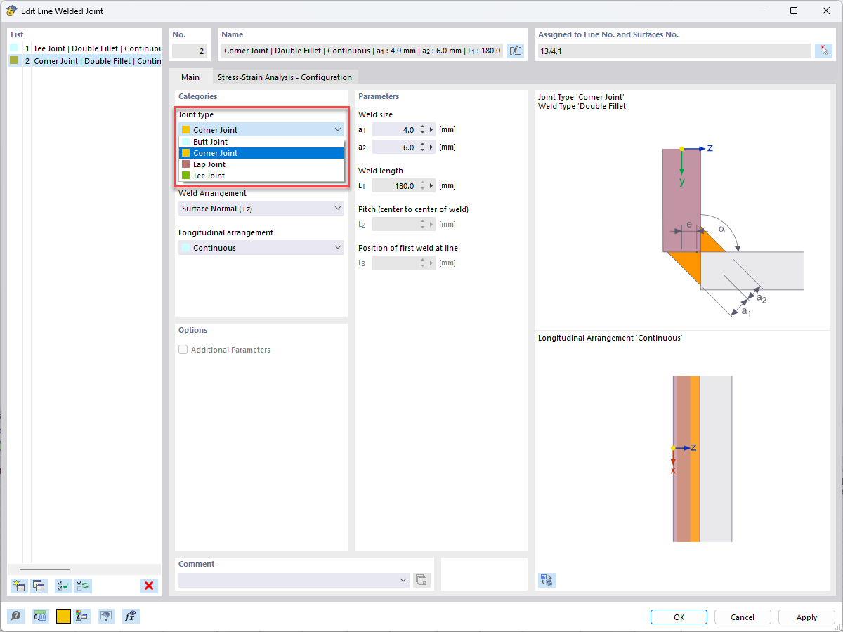
Welds in RFEM 6
In the case of stairs with a complicated geometry, it is often difficult to design welds by using the analytical methods. How can I do this with RFEM?
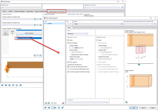
Member Design Supports for Deflection Checks
How do I define a member as a cantilever and not as supported at both ends for serviceability or deflection design?
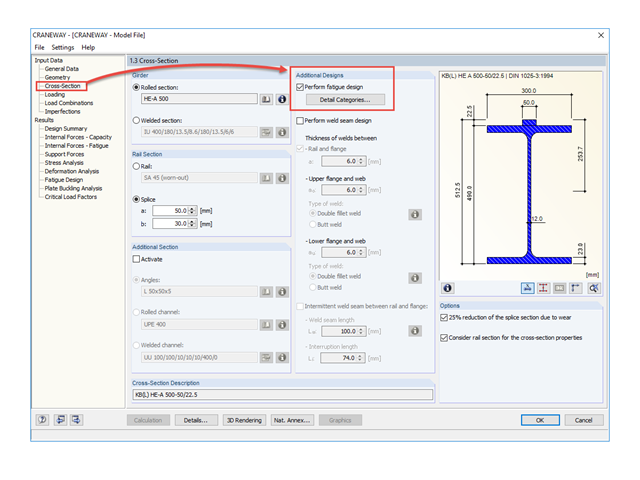
Fatigue Design
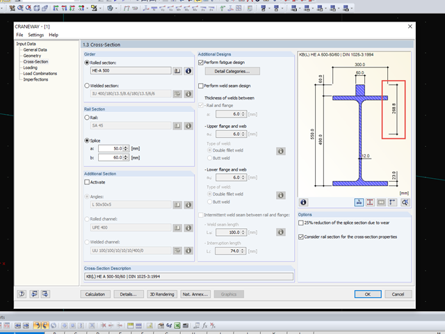
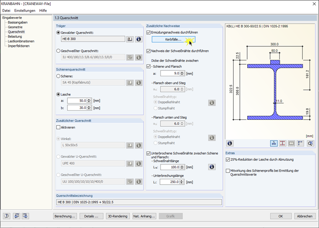
Where is the fatigue design activated in the CRANEWAY program?
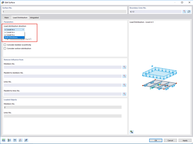
Directions of Load Distribution
I have a girder grid with members in the X- and Y-directions. After applying a load using the "Load Distribution" surface type, the members are only loaded in one direction.
How can I load all the members?
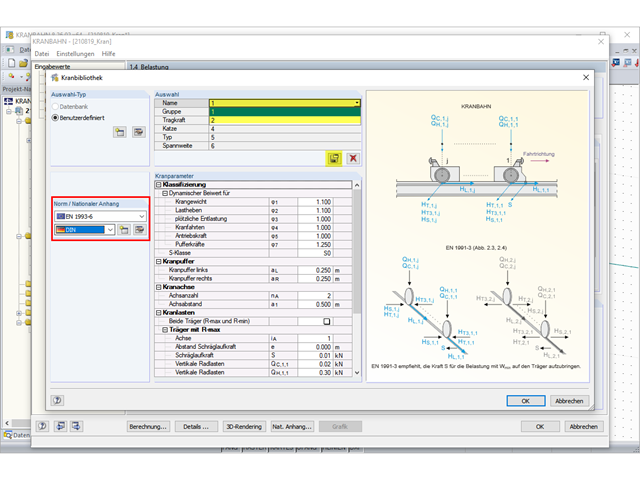
Crane Library
In CRANEWAY, there is a crane library with templates. Why is it grayed out?
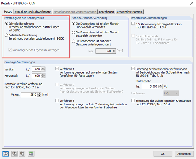
Question
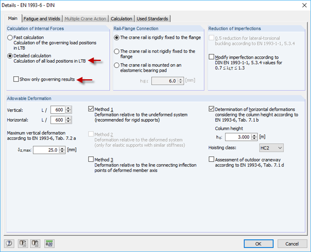
How can I optimize the calculation time in CRANEWAY?
Question
Where can I find the determined support forces for the crane runway girder? At the bottom flange of the crane runway girder or in the shear center of the cross-section?
Question
Is it possible to manually adjust detail categories or a stress cycle of the detail categories?
Question
How can I obtain internal forces, calculated in CRANEWAY, for a special x-location?
Entering Sway Bracing in RFEM or RSTAB
How can I consider a sway bracing in CRANEWAY?
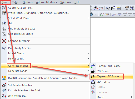
Generate truss
Is it possible to quickly generate a truss girder with RFEM and RSTAB?
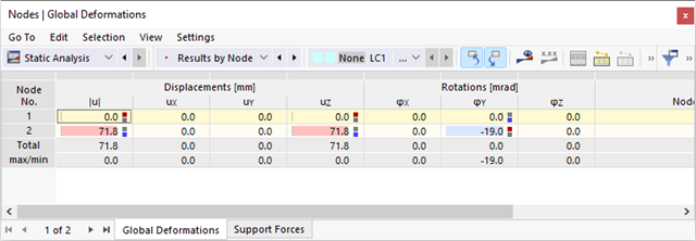
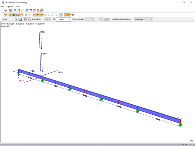
Deformations of Craneway
I am trying to manually check the deformations from the CRANEWAY add-on module. However, I obtain large deviations. How to explain the differences?
Question
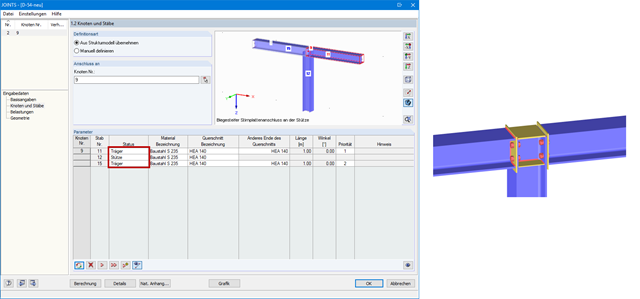
How can I model and design a crane runway girder with Dlubal Software?
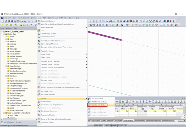
Question
How can I create a drilled beam in RFEM?
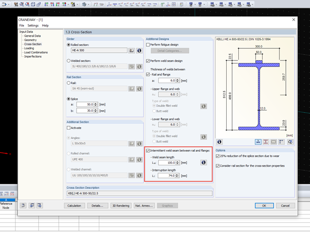
Question
Is it possible to design intermittent welds in the CRANEWAY add-on module?

Question
Is the load on beams correct when transferring the data of the crane data sheet to CRANEWAY with the correct sign?
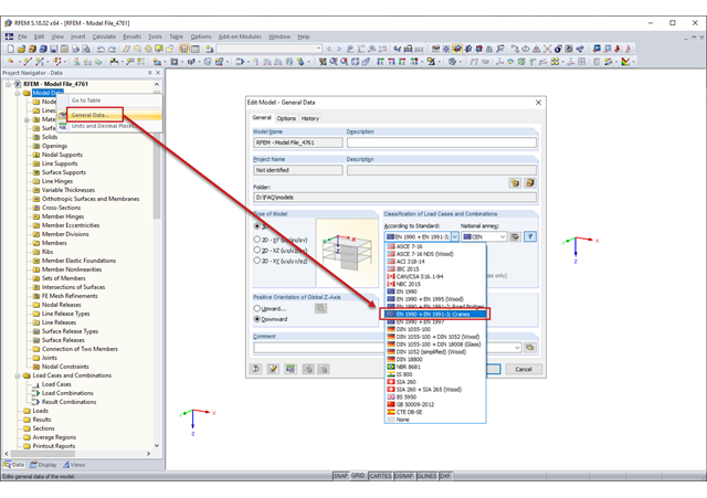
Question
Where can I find the action category for cranes in my load cases?
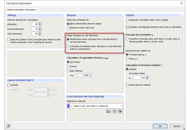
Question
How can I display shear stresses on null elements in SHAPE‑THIN?
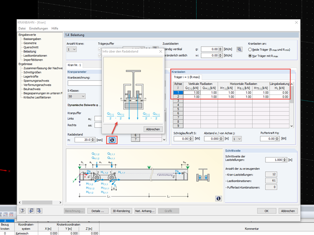
Question
Is it necessary to enter the loads of a crane for each axle or wheel in the table of crane loads in Window 1.4?
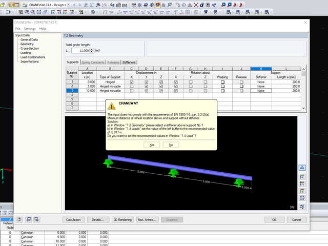
Question
Is it possible to design a crane runway girder without stiffeners on supports in CRANEWAY?
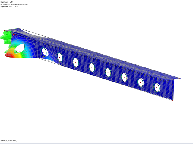
Question
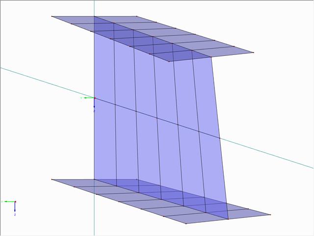
I have calculated a box girder. Which surface results or surface stresses can I use to evaluate the buckling behavior of the web plates?
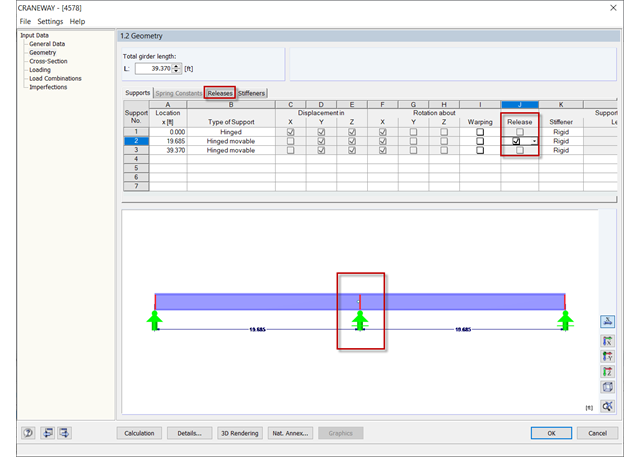
Question
How can I model several simply supported beams in a row in CRANEWAY?
Question
What is the difference between the dongle drivers of CRANEWAY and RFEM or RSTAB?
Question
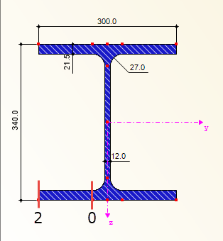
I would like to use the CRANEWAY add-on module to design a suspension crane. Where are design points 0, 1, and 2 for the stress analysis on the bottom flange and for the fatigue design?